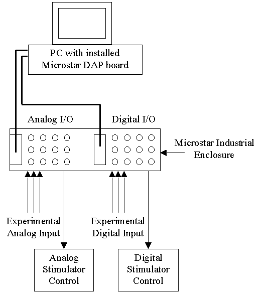
 DAPSYS combines a Data Acquisition Processor (DAP) board with a Pentium-based PC. The DAP board is designed by Microstar Laboratories and uses a AMD K6 processor within an architecture specialized for high-speed data acquisition and processing. The DAP board is installed into one of the PC PCI slots and communicates with the PC resources through the PC bus. It runs its own real-time operating system and is a distinct "computer" within the physical confines of the PC chassis. In this discussion, then, it will be convenient to distinguish the DAP board from the PC itself.
To describe the hardware for DAPSYS, we trace an input signal path through the system. On the diagram, "Experimental Analog Input" might refer to an amplified neural electrical signal collected from a surgical attachment or it might be the voltage output of a stimulator such as a mechanical or thermal stimulator. The "Experimental Digital Input" might be a triggering pulse generated by a piece of laboratory equipment such as an electrical stimulator.
The signal enters DAPSYS through the Microstar Industrial Enclosure, which provides standard BNC jacks for connection to laboratory equipment. The industrial enclosure also multiplexes the input data for input to the PC through the two cables shown. This industrial enclosure can be easily reconfigured and expanded to handle a variety of experimental data collection needs.
On the back of the PC, the cables running from the industrial enclosure connect to the analog and digital I/O connectors of the DAP board. The input signal enters the DAP board through its buffered input section and is then conditioned by various specialized routines and sent to the PC through the PC bus. The PC software displays and stores the data received from the DAP board. DAPSYS also provides stimulator control synchronized with the data collection. On the diagram, this begins with the PC and generally follows the same path as data input but in reverse-order and ending with the "Analog Stimulator Control" and "Digital Stimulator Control" boxes shown. The exact front panel connections of the Industrial Enclosure can be configured differently depending on the application.
Typically there are up to 10 analog inputs and 2 analog outputs on the left panel of the Industrial Enclosure and 8 digital input and 8 digital outputs on the right panel of the Industrial enclosure.